
Tamping Roller
 1. INTRODUCTION
Under repeated loading from traffic the track progressively moves, causing deviations from the desired vertical and horizontal alignment. Ballast tamping is the process to restore the geometry and re-arrange the ballast under the sleeper to keep the track in position and provide it with a homogenous ballast bed. The track geometry should be measured regularly or at least, the track should be tamped at regular intervals to ensure that trains are able to travel safely at the normal speed of the line.
When using inferior machines or other manual tamping methods, geometry is corrected using track jacks and the visual judgement of the Track Master. These methods are not able to provide the quality or durability required for a modern railway line. On any modern railway today, tamping machines with automated lifting, lining and synchronised tamping on open track, turnouts, checked rail sections, splice joints etc. is essential for maintaining the track at the required standards.
Selecting the right machine for the particular track with regards to traffic, length, axle loading, number of turnouts, checked rail sections, spice joints, restricted track etc, has become quite a science. To do so one needs to have a good understanding of the machine types available, their components and functions in order to select the most cost effective solution.
 2. BASIC TAMPING PROCESS
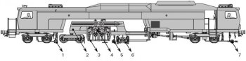
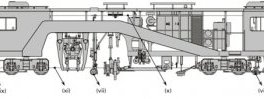
The most important working components of a tamping machine are shown in Figure 1.
1 – Rear Measuring Trolley 5 – Centre Measuring Trolley
2 – Satellite (Continuous Action) 6 – Lifting and Lining Unit
3 – Tamping Unit Frame 7 – Front Measuring Trolley
4 – Tamping Unit/s
Figure 1: Working Components of Tamping Machine
(09-3X Continuous Action Tamping Machine Illustrated)
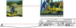
Figure 2 provides a schematic illustration of the tamping process in 4 simplified steps.
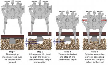 Step 1 – A basic tamping machine indexes forward and comes to a standstill with the tamping tines of the tamping unit straddling the sleeper to be tamped on both sides.
Step 2 – The lifting and aligning unit works in conjunction with the measuring system and grips the rail under the crown, lifts the track to a predetermined height while correcting any vertical alignment defects in the track and at the same time slews the track to correct the horizontal alignment (simultaneous levelling and aligning).
Step 3 – The tamping units are lowered. The vibrating tines enter the ballast and stop at a pre-determined depth. The tines are vibrating in order to fluidise the ballast stone to permit it to re-arrange and settle in a dense matrix. Controlled vibration greatly reduces the force required to penetrate the tamping tines into the ballast without damaging or crushing the ballast stone.
Step 4 – The cylinder assembly exerts a force on the tine arms which perform a squeezing motion of the tines. The tines compact ballast underneath the sleeper in the void created by the lifting process. The tamping machine indexes forward to the next sleeper and the process repeats itself. Behind the tamping machine the track is left at the required geometric standard on a homogeneous ballast bed with restored elasticity.
 3. A SPECIALISED TAMPING MACHINE FOR EVERY APPLICATION
3.1. Plain Track Tamping Machines
Plain track tamping machines are designed for high production tamping on tangent track on busy lines where the maximum number of sleepers must be tamped in short available maintenance windows. They use technologies such as continuous action tamping and tamping up to 4 sleepers per insertion.
There are, however, many different plain track tamping machine models and not all of them are focused on maximum production, since conditions vary from railway to railway and even between track sections within the same railway.
3.2. Universal Tamping Machines
In turnouts, crossings, splice joints, checked rail sections and other restricted track, some tines may be obstructed by the turnout rails, switch blade, etc. Turnout tamping machines must therefore have specialised tamping units capable of working in these restricted areas, lifting units capable of lifting the track with restricted space, third-rail lifting devices to lift the long sleepers, tamping unit frames that can slew sideways to centre the tamping unit over diverging rails, etc.
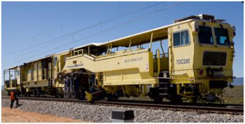
Universal tamping machines, such as the DYNA-CAT shown in Figure 3 are equally capable of tamping plain track at tamping rates similar to plain track tamping machines of the same size.
4. TAMPING MACHINE COMPONENTS
In the previous paragraphs reference was made to the following tamping machine components and features:
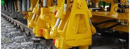
4.1. Lifting and Aligning Unit
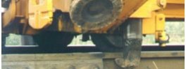
Tamping machines are equipped with a combined lifting and aligning unit (i) mounted in front of the tamping units (ii) between the bogies (see Figure 4). There are various designs depending on the machine type but they can generally be divided between lifting and aligning units for universal tamping machines and those for plain track tamping machines.
Share this article
Related Posts

Latest Posts


